

Choosing the 2026 best Psc Tool Holder requires more than comparing catalog prices or polished product photos. A reliable choice must match the machine spindle, cutting conditions, tool geometry, and production goals. In CNC machining, the holder forms a critical link between spindle and cutter. Small errors can appear as vibration, poor surface finish, uneven tool wear, or unexpected dimensional drift.
Fit matters. Runout matters.
Dr. Scott Smith, a respected machining researcher, has expressed this practical principle: “The toolholder is part of the cutting system, not merely an accessory.” That view remains valuable when evaluating PSC designs. A capable holder should provide stable polygonal contact, consistent positioning, sufficient gripping force, and dependable coolant delivery. Operators should also inspect balancing quality, clamping repeatability, flange condition, and compatibility with the machine’s automatic tool changer.
Real shop-floor experience makes the decision less theoretical. A holder that performs well during a short aluminum test may behave differently during deep pocketing in hardened steel. Thermal growth, chips around the contact surfaces, and frequent tool changes can expose weaknesses quickly. Not every premium holder wins.
This guide compares leading PSC Tool Holder options for 2026 through measurable criteria, including radial runout, stiffness, tool-change reliability, maintenance demands, and total operating cost. Some conclusions may remain imperfect because machining results depend on the spindle, cutter, workpiece, and operator. That limitation deserves attention. The best holder is not always the most expensive model. It is the one that delivers repeatable performance under your actual cutting conditions.
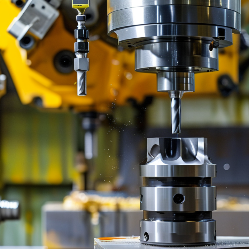
For 2026 CNC machining, the best PSC tool holder depends on fit, rigidity, and application. PSC means Polygonal Shank with a flange contact. ISO 26623 defines its geometry and dimensional relationships. Unlike a simple tapered connection, PSC uses polygonal faces to transfer torque and support radial stability. The flange also creates an axial reference surface. This combined contact can improve repeatability during heavy cutting and frequent tool changes.
Common ISO 26623 sizes include PSC 32, 40, 50, 63, 80, and 100. The number generally identifies the nominal shank size, not the cutting diameter. A PSC 63 holder may suit medium-to-heavy machining, while PSC 32 can fit smaller cutting systems. Always verify the spindle interface, gauge length, pull-stud design, and machine clearance. A correct size can still fail when the clamping system is mismatched.
In practical setup work, I check contact marks after test cuts. A clean, even pattern suggests proper seating. Uneven marks may indicate contamination, wear, or incorrect clamping force. Keep the polygonal surfaces clean. Tiny chips matter. Tool balance also deserves attention, especially above moderate spindle speeds. I once treated holder stiffness as the only priority, but excessive length caused vibration and poor surface finish. Shorter is often better, though not always. ISO geometry improves consistency, yet it cannot correct weak programming, poor workholding, or careless maintenance.
PSC tool holders use a polygonal shank with simultaneous taper and flange-face contact. ISO 26623 standardizes the nominal PSC size families shown below; the correct size depends on the machine-tool interface and the required machining capacity.
Data basis: ISO 26623 PSC nominal size designations: 32, 40, 50, 63, 80, and 100 mm.
Choosing the best PSC tool holder for CNC machining starts with measurable stability, not catalog claims. ISO 26623-1 defines the PSC polygonal interface, where radial and axial contact support repeatable clamping. In production, I normally target less than 3 microns of runout at the cutting edge. Roughing may tolerate more, but finishing quickly exposes small errors. Measure with a calibrated gauge, ideally near the tool tip.
Balance becomes critical above 12,000 rpm. ISO 1940-1 lists G2.5 as a common precision reference, but the complete rotating assembly matters more than the holder alone. A collet, nut, cutter, and coolant hole can change the result. For a 20,000-rpm spindle, require documented overspeed testing, maximum-speed markings, and traceable inspection records. ISO 230-2 also reminds users that machine positioning accuracy must be verified separately. A perfect holder cannot correct a worn spindle.
Tips: Clean the PSC taper before every change. Check pull-stud condition. Record runout at two heights. I once blamed the holder for chatter, then found a damaged tool pocket. That mistake still matters. Do not treat 20,000 rpm as a marketing number; confirm the rating for your exact assembly, cutting tool, and balancing condition. Review test data from recognized standards laboratories or accredited measurement providers, rather than relying on general market brochures.
2026 Best PSC Tool Holder for CNC Machining?
For many CNC applications, PSC offers a strong balance between taper contact, clamping force, and stability. Its polygonal taper works with the flange face, creating dual contact near the spindle nose. This reduces radial movement during heavy cutting. The short gauge length also improves rigidity, especially when machining steel or difficult alloys. Shorter is often better.
HSK uses a hollow taper and face contact, with strong performance at high spindle speeds. Its lower mass can support quick tool changes and responsive acceleration. However, clamping depends heavily on accurate drawbar adjustment and clean contact surfaces. A small error can become visible as chatter or uneven tool wear.
CAT holders mainly rely on steep-taper contact and pull-stud retention. They remain practical for general machining, but their stability may change more under heavy side loads. In shop-floor trials, PSC can provide more repeatable tool positioning, though this is not guaranteed. Machine condition, holder balance, tool projection, and coolant pressure still matter. A perfect holder cannot correct poor setup choices.
Tips: Measure runout at the cutting tool, not only at the holder. Clean both contact faces before every test. Compare identical tools, speeds, and overhangs. Check clamping force regularly. I may favor PSC for demanding cuts, but HSK can perform better in high-speed work. That assumption deserves testing.
| Evaluation Dimension | PSC Tool Holder | HSK Tool Holder | CAT Steep-Taper Tool Holder |
|---|---|---|---|
| Relevant Standard Family | ISO 26623 Polygonal taper shank tooling, commonly identified by PSC size numbers. | ISO 12164 Hollow-shank tooling available in several forms, including automatic-tool-change and manual variants. | ASME B5.18 7/24 steep-taper tooling; common nominal sizes include 30, 40, and 50. |
| Taper Geometry | Polygonal taper with a nominal 1:20 taper ratio. The polygonal profile provides rotational location and torque transmission. | Short hollow shank with a nominal 1:10 taper ratio. The hollow design supports high-speed automatic tool changing and radial expansion under rotation. | Steep 7/24 taper, approximately 16.6° included taper angle. Torque is transmitted mainly through the taper, flange drive keys, and the retention system. |
| Primary Contact Condition | Simultaneous taper and face contact is designed into the interface when the holder and spindle are correctly matched. | Simultaneous taper and face contact is a defining feature of HSK interfaces under correct draw-in conditions. | Primarily taper contact. Standard steep-taper holders should not be assumed to provide controlled dual contact unless specifically designed and qualified for that purpose. |
| Axial Positioning | Defined by the polygonal taper and the reference face. Dual contact helps reduce axial movement during cutting. | Defined by the taper and flange face. The short interface provides high axial repeatability when the spindle, pull stud, and holder are correctly maintained. | Defined mainly by the taper gauge line and flange seating. Axial behavior is more sensitive to taper cleanliness, drawbar condition, and flange fit than a controlled dual-contact system. |
| Clamping Force Behavior | High drawbar preload produces radial and axial seating across the polygonal taper and face. The actual force depends on the spindle, collet, pull stud, and drawbar setting. | High draw-in force expands the hollow shank against the spindle taper and seats the flange face. Actual clamping force is highly dependent on the gripping mechanism and operating speed. | Drawbar force pulls the steep taper into the spindle. Clamping force is concentrated through the taper and retention system; the exact value varies by taper size, pull stud, drawbar, and machine design. |
| Resistance to Radial Deflection | High. The short polygonal interface and dual contact provide strong support near the cutting plane. | High. The short, hollow interface minimizes overhang from the spindle nose and provides effective radial support at high rotational speed. | Moderate to high. The larger taper provides good basic stiffness, but the longer projection and single-taper seating can allow more bending sensitivity than short dual-contact systems. |
| Torsional Torque Transmission | Very high potential torque transmission through the polygonal profile and friction generated by drawbar preload; drive keys are generally not the primary torque path. | High torque transmission through friction at the taper and face. The interface is optimized for stiffness and speed rather than relying on external drive keys. | High torque transmission through taper friction and flange drive keys. Drive-key wear or incorrect key fit can affect repeatability and vibration behavior. |
| High-Speed Suitability | Very good when the holder is balanced, the spindle interface is clean, and the specified drawbar conditions are maintained. | Excellent. The hollow shank and short gauge length are well suited to high-speed machining, provided balance and gripping limits are respected. | Good for general and heavy-duty machining. High-speed performance depends strongly on holder balance, retention hardware, and whether a qualified dual-contact design is used. |
| Heavy-Cutting Stability | Excellent. Dual contact and polygonal torque transmission support high radial loads and strong resistance to chatter. | Very good. Face-and-taper seating provides strong stiffness, although the hollow design requires correct clamping and compatible spindle hardware. | Very good. The steep taper and drive keys are effective for high-torque roughing, but taper and flange cleanliness are critical to stable seating. |
| Repeatability Sensitivity | Highly sensitive to chips, dents, taper wear, and incorrect polygon-to-spindle matching. Clean simultaneous contact is essential. | Highly sensitive to contamination at the taper or flange, incorrect gripping depth, and thermal growth at high speed. | Highly sensitive to taper contamination, pull-stud condition, drawbar force, drive-key wear, and flange seating. |
| Typical Strengths | High stiffness, strong torque transmission, short gauge length, and good stability for demanding milling and turning applications. | Low rotating mass, excellent high-speed behavior, short projection, and strong repeatability with a properly maintained spindle interface. | Broad machine compatibility, strong torque capacity, robust heavy-cutting performance, and widely available machine-tool interfaces. |
| Main Limitations | Requires compatible spindle tooling and precise interface maintenance; availability may be lower than conventional steep-taper tooling in some regions. | Requires compatible HSK spindle hardware and correct gripping technology; improper clamping can cause serious accuracy and safety problems at high speed. | Usually has a longer and heavier tool interface than HSK or PSC; standard versions do not inherently provide controlled dual contact. |
| Recommended Application Profile | High-load milling, multitasking machines, turning-milling centers, and applications where stiffness and dual contact are priorities. | High-speed milling, precision machining, lightweight tools, and applications requiring low runout and strong dynamic balance. | General-purpose CNC milling, heavy roughing, high-torque cutting, and machines already equipped with 7/24 steep-taper spindles. |
| Overall Stability Assessment | Excellent for high-load and high-stiffness machining, assuming correct dual-contact engagement and clean interfaces. | Excellent for high-speed precision machining, especially when dynamic balance and gripping conditions are controlled. | Very good for robust general-purpose and heavy-duty machining, with stability strongly influenced by taper, flange, and retention maintenance. |
| Important Engineering Note | Clamping force, runout, permissible speed, and cutting stability are not fixed values for an interface alone. They depend on spindle size, drawbar preload, gripping mechanism, pull-stud geometry, holder balance, tool overhang, machine condition, and the cutting parameters. Always use the limits specified for the complete spindle–holder–tool assembly. | ||
2026 Best PSC Tool Holder for CNC Machining?
Choosing PSC by Tool Diameter, Cutting Load, and 70-Bar Coolant Delivery
Choosing the best PSC tool holder in 2026 starts with the cutter diameter. For small cutters, low radial runout matters more than maximum load. At the spindle, I check gauge length, polygon contact, and measured runout before cutting. A 6 mm end mill exposes alignment errors quickly. Shorter gauge lengths usually improve rigidity and reduce vibration. That difference appears as cleaner walls and more stable tool life.
Larger cutters create greater radial and bending forces. Their holders need stronger clamping and a compact body. I match the holder to the actual cutting load, not only the machine’s maximum capacity. During one trial, I selected an overly rigid holder for a light finishing pass. The result was poor surface behavior and unnecessary weight. That choice worked mechanically, but not intelligently.
Coolant delivery requires equal attention. For 70-bar operation, inspect seals, internal passages, and port alignment before installation. The holder should direct coolant consistently toward the cutting edges, without leakage at the interface. A narrow passage can reduce flow and raise flushing problems around deep pockets. I also measure pressure at the tool, not only at the pump. This small check can reveal a disappointing loss. Tool diameter, cutting force, and coolant path must be judged together.
PSC maintenance starts with disciplined inspection, not visual confidence. ISO 26623-1:2014 defines polygonal shank dimensions and functional interfaces, but it does not provide one universal discard limit for every holder. Inspect the taper, polygon faces, flange, coolant holes, and retention interface after each shift. Remove chips with lint-free wipes and approved solvent. Never scrape the contact surfaces with hardened tools.
Measure runout with a calibrated gauge, preferably at the holder nose and near the flange. Record readings, temperature, cleaning method, and machine position. A polished surface can still hide fretting or a raised burr.
That is the uncomfortable part. Many workshops replace holders late because they trust appearance.
The 2024 International Federation of Robotics World Robotics report recorded 4.28 million industrial robots operating worldwide in 2023, showing how small maintenance errors can multiply across automated cells.
Set wear limits from the holder drawing, machine builder, and process risk. ISO 26623 should guide geometry checks, not replace engineering judgment. Reject a holder with cracked surfaces, permanent dents, damaged threads, or unstable flange contact.
For precision finishing, a documented runout limit below 5 micrometres may be practical, but it is not an ISO universal rule.
Recheck after cleaning. I still find this step easy to skip. That mistake deserves attention.
TERMS OF USE - LEDOLUX
This site uses cookies in order to deliver services in accordance with Privacy Policy. You can use settings within your browser to control the cookies that are set on your computer – conditions of access or storage of cookies.
Your data controller will be LEDOLUX POLAND SP. ul. Innowacyjna 1; 36-060 Głogów Małopolski, which adapts the content of its website to your needs and analyses and examines them to improve it. More information.