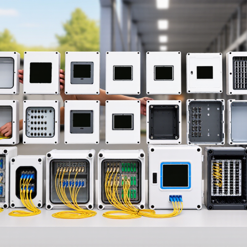
Fiber access networks are expanding from urban cabinets to apartment buildings, campuses, and remote communities. The FTTH Council Global Alliance continues to report strong global growth in fiber-to-the-home deployments. Its market updates show rising fiber coverage, subscriber adoption, and investment across mature and emerging regions. That growth increases the need for organized, serviceable termination points.
A 24 Port Fiber Termination Box provides a compact interface between incoming feeder cables and customer-side distribution fibers. Inside a typical enclosure, technicians may find splice trays, adapter panels, pigtails, cable glands, bend-radius guides, and labeling areas. Small details matter. A poorly secured cable can create excessive fiber loss or difficult maintenance later.
This guide examines 24 leading termination box types for 2026. The comparison considers wall-mounted, rack-mounted, outdoor, indoor, lockable, waterproof, modular, and high-density designs. It also considers SC, LC, and other connector configurations. IEC 61754 connector standards and IEC 61300 testing practices provide useful technical reference points for compatibility and performance. CRU’s fiber broadband research and FTTH Council deployment reports further confirm the importance of scalable fiber infrastructure.
However, no universal ranking fits every network. Climate, cable diameter, installation space, splice capacity, and security requirements can change the best choice. Some product categories overlap. That is worth admitting.
Practical selection should begin with the site, not the brochure. A dusty roadside cabinet demands different protection from a clean indoor telecom room. This overview therefore combines published specifications, installation experience, and reliability-focused evaluation. The goal is a clearer shortlist for network planners, contractors, and maintenance teams.
A 24-Port Fiber Termination Box is a passive enclosure that organizes and protects optical fiber connections. It receives feeder fibers, then splices or terminates them across 24 adapter positions. Each port provides a defined connection point for distribution cables. The enclosure also protects fibers from dust, pulling force, and excessive bending. It is not an active network device. That distinction matters.
The ITU’s Facts and Figures 2024 estimated that 5.5 billion people were online, representing 68% of the global population. The FTTH Council Europe Market Panorama 2024 reported over 244 million homes passed by FTTH/B networks across Europe in 2023. This expansion increases demand for compact, orderly fiber distribution. A 24-port box fits apartment risers, campus closets, and neighborhood cabinets. Technicians can label ports, manage splice trays, and inspect connections without disturbing the entire route.
Port count alone is not enough. Check connector type, splice capacity, cable entry, sealing performance, and mounting method. IEC 61753 and IEC 61754 references support verification of environmental and connector performance. Local specifications still control the final choice. A common mistake is ignoring working space behind the tray. I would not specify a box by capacity alone. Faded labels, tight slack, and poor polarity records can create avoidable faults. The hardware may look adequate. The installation may not be.
What Is a 24-Port Fiber Termination Box?
A 24-port fiber termination box provides a protected point for organizing, terminating, splicing, and testing optical fibers. The chart compares the theoretical fiber positions available when a 24-position panel uses different connector formats: SC simplex carries one fiber per connector, LC duplex carries two, MPO-12 carries twelve, and MPO-24 carries twenty-four.
The 24-port fiber termination box is available in several designs for different network environments. Wall-mounted boxes suit offices, buildings, and compact communication rooms. Rack-mounted versions fit standard cabinets and keep patch cords aligned. Modular boxes allow technicians to replace adapters, trays, or panels without changing the whole enclosure.
Installation design matters as much as port capacity. Indoor boxes usually use lightweight metal or flame-retardant plastic housings. Outdoor models need sealed joints, cable glands, grounding points, and stronger protection against dust and moisture. Splice-based boxes protect fusion splices inside trays, while patch-panel designs provide quicker testing and port replacement. Front-access structures work well in crowded racks. Rear-access models can offer cleaner cable routing, but maintenance becomes less convenient. I have seen installers choose a neat box that later restricted bend radius. That mistake is easy to miss.
Tips: Check fiber bend radius, adapter type, cable entry direction, and available slack before installation. Leave enough tray space for future repairs. Label every port clearly. Test insertion loss and return loss after termination. A visual fault locator can reveal sharp bends quickly. Do not force a crowded closure. Technicians should also inspect grounding and sealing after outdoor installation. Some designs look sealed but fail when cable glands are poorly tightened. A second inspection is worthwhile.
| No. | 24-Port Fiber Termination Box Type | Design Configuration | Typical Fiber Interface | Fiber Capacity | Installation Method | Typical Enclosure Material | Common Application |
|---|---|---|---|---|---|---|---|
| 1 | Standard Wall-Mount Termination Box | Fixed front adapter panel with internal splice tray and cable management area | 24 LC duplex or 24 SC simplex | Up to 24 terminated fibers; optional splice storage for 24 fibers | Indoor wall mounting with screws and wall anchors | Powder-coated steel or ABS plastic | Building entrance rooms, telecom closets, and structured cabling systems |
| 2 | Compact Wall-Mount Distribution Box | Low-profile enclosure with adapter field and compact bend-radius guides | LC duplex, SC simplex, or mixed adapter plates | 24 ports; commonly supports 24 to 48 spliced fibers depending on tray layout | Indoor wall mounting in space-limited areas | ABS, polycarbonate, or painted steel | Office floors, small data rooms, and access network distribution points |
| 3 | Lockable Wall-Mount Fiber Box | Hinged or removable front cover with a keyed or tool-operated lock | 24 SC simplex, 24 LC duplex, or MPO adapter modules | 24 front-access termination ports with protected splice storage | Wall mounting in controlled indoor or semi-outdoor areas | Cold-rolled steel or reinforced polycarbonate | Public buildings, apartment complexes, and shared telecommunications rooms |
| 4 | Outdoor Weatherproof Termination Box | Sealed hinged enclosure with cable glands, gasketed door, and splice protection | 24 SC simplex or LC duplex adapters | 24 terminated fibers; splice capacity varies with tray selection | Wall, pole, or cabinet mounting | UV-resistant polycarbonate, ABS, or powder-coated metal | Outdoor access networks, campus links, and building exteriors |
| 5 | Pole-Mount Fiber Termination Box | Vertical enclosure with pole brackets and compact cable-entry arrangement | SC simplex, LC duplex, or hardened optical adapters | 24 ports with separate slack-fiber and splice compartments | Metal-band or bracket attachment to utility and lighting poles | UV-stabilized polycarbonate or aluminum | Aerial access networks, surveillance systems, and roadside communications |
| 6 | Rack-Mount Fiber Termination Panel | 19-inch rack chassis with modular front adapter plates and rear cable access | 24 LC duplex, 24 SC simplex, or mixed-format modules | 24 ports; may include splice trays for 24 to 48 fibers | Mounted in a standard 19-inch equipment rack or cabinet | Steel chassis with aluminum or steel adapter panels | Data centers, carrier rooms, and enterprise network cabinets |
| 7 | 1U Sliding Rack-Mount Fiber Box | Pull-out sliding drawer with front adapters and rear splice management | 24 LC duplex or 24 SC simplex adapters | 24 ports with practical access to splices and pigtails | Horizontal installation in a 19-inch rack | Powder-coated steel with sliding metal rails | High-density patching where front maintenance access is important |
| 8 | Fixed 1U Rack-Mount Patch Panel | Non-sliding panel with fixed adapter plates and rear cable-routing space | 24 LC duplex or 24 SC simplex ports | 24 terminated fibers; limited internal splice storage | Fixed mounting in a 19-inch rack or cabinet | Steel panel with removable adapter plates | Simple fiber cross-connects and patch-only installations |
| 9 | High-Density LC Termination Box | Compact adapter arrangement optimized for small-form-factor LC connectors | 24 LC duplex ports, equivalent to 48 LC fiber positions | 24 duplex ports; commonly used for 48 individual fibers | Rack, wall, or cabinet mounting depending on chassis design | Steel or aluminum enclosure | Data center links, switch uplinks, and high-density backbone patching |
| 10 | SC Duplex-Compatible Termination Box | Adapter panel arranged for larger SC connector bodies and easy finger access | 24 SC duplex adapters | 48 fiber positions when duplex adapters are used | Wall, rack, or cabinet installation | Painted steel or molded polymer | Telecommunications rooms and legacy single-mode fiber systems |
| 11 | MPO/MTP Modular Termination Box | Modular cassette or adapter-panel design for pre-terminated multi-fiber trunks | 24 MPO or MTP interfaces, or a combination of MPO and LC cassettes | Capacity depends on polarity and module configuration; commonly supports multiple 8-, 12-, or 24-fiber circuits | Rack, cabinet, or wall mounting using a modular chassis | Steel chassis with polymer cassettes | Parallel optics, structured cabling, and high-density data center distribution |
| 12 | Splice-and-Termination Box | Integrated adapter field, fusion-splice trays, pigtail storage, and cable slack area | LC duplex, SC simplex, or SC duplex | 24 terminated ports plus organized splice capacity | Wall or rack mounting | Steel, aluminum, or reinforced polymer | Feeder-to-distribution transitions and permanent fiber consolidation |
| 13 | Pre-Terminated Pigtail Distribution Box | Factory-installed pigtails routed to splice trays and adapter panels | 24 LC, SC, or FC adapter positions | 24 pigtail terminations with matching splice storage | Wall, rack, or cabinet mounting | Powder-coated steel or aluminum | Installations requiring shorter field preparation time |
| 14 | Field-Installable Termination Box | Empty enclosure with removable panels for on-site adapter and splice assembly | Interchangeable LC, SC, or FC adapter plates | Up to 24 ports, configurable by connector type | Wall, rack, or cabinet installation | Steel or flame-retardant engineering plastic | Projects with changing connector requirements or phased deployment |
| 15 | DIN-Rail Fiber Termination Box | Compact enclosure with clips or brackets for standard industrial DIN rails | LC duplex, SC simplex, or industrial fiber adapters | Typically 24 ports across one or more compact modules | DIN-rail mounting inside control cabinets | Aluminum, steel, or flame-retardant polycarbonate | Industrial Ethernet, substations, transportation, and automation networks |
| 16 | Industrial-Rated Fiber Termination Box | Reinforced enclosure with improved sealing, strain relief, and vibration resistance | LC, SC, or ruggedized industrial connectors | 24 ports with segregated cable-entry and termination zones | Wall, panel, or cabinet mounting in industrial facilities | Powder-coated metal or impact-resistant polycarbonate | Factories, process control areas, and harsh indoor environments |
| 17 | Front-Access Fiber Termination Box | All adapters, splice trays, and cable-management features are serviceable from the front | 24 LC duplex or 24 SC simplex ports | 24 terminated ports with front-access splice organization | Shallow wall, cabinet, or rack installation | Steel or aluminum | Closets with limited rear clearance and dense cabinet layouts |
| 18 | Rear-Access Fiber Termination Box | Front adapter field with rear cable routing and termination access | LC duplex, SC simplex, or FC adapters | 24 ports with larger rear cable-management space | Rack or cabinet installation where rear service clearance is available | Powder-coated steel | Central equipment rooms and organized backbone distribution frames |
| 19 | Splice Tray Integrated Fiber Box | Stackable splice trays with dedicated bend-radius control and adapter panel | LC, SC, or FC connector panels | 24 ports with expandable splice-tray capacity | Wall, rack, or cabinet mounting | Steel enclosure with ABS or polycarbonate trays | Fiber restoration points and networks requiring structured splice access |
| 20 | Sliding Cassette Fiber Termination Box | Removable or sliding cassette modules for adapter, splice, and splitter functions | LC duplex, SC simplex, or MPO-based cassettes | 24 ports distributed across replaceable cassettes | Rack, cabinet, or wall mounting using a cassette chassis | Steel chassis with molded polymer cassettes | Modular networks requiring quick reconfiguration and maintenance |
| 21 | Splitter-Integrated Fiber Termination Box | Termination panel combined with passive PLC or FBT splitter compartments | SC, LC, or connectorized splitter outputs | 24 output ports; splitter ratio and input count vary by design | Wall, cabinet, or outdoor enclosure installation | Steel, aluminum, or sealed polycarbonate | Passive optical networks and fiber-to-the-building distribution |
| 22 | Fiber-to-the-Home Distribution Box | Subscriber-oriented enclosure with feeder splice area and multiple distribution ports | SC/APC, LC/APC, or connectorized drop-fiber interfaces | 24 subscriber or distribution ports, depending on splitter architecture | Indoor wall, outdoor wall, pole, or cabinet mounting | UV-resistant polycarbonate or powder-coated metal | Residential broadband, multi-dwelling units, and neighborhood access networks |
| 23 | Aerial Fiber Termination Box | Weather-resistant enclosure designed for suspended or strand-mounted cable routes | SC, LC, or hardened optical connector interfaces | 24 ports with cable slack and splice management | Aerial strand, messenger-wire, or pole installation | UV-resistant polymer or corrosion-resistant metal | Aerial distribution, rural broadband, and roadside fiber routes |
| 24 | Cabinet-Mounted Fiber Termination Box | Compact panel or subassembly installed inside an outdoor communications cabinet | 24 LC duplex, SC simplex, or mixed connector positions | 24 terminated ports with optional splice, splitter, and slack-fiber sections | Equipment cabinet, street cabinet, or pedestal installation | Steel, aluminum, or reinforced polycarbonate | Municipal networks, outside-plant cabinets, and access aggregation points |

Fiber capacity determines how comfortably a termination box supports present and future network demand. Common options include 4, 8, 12, 24, and 48 ports. A 24-port enclosure often suits access cabinets, building risers, and compact distribution panels. However, unused capacity still consumes space and budget. Bigger is not always better.
Connector choice affects installation speed, maintenance, and optical performance. LC adapters save panel space and suit high-density layouts. SC adapters offer a larger housing and simpler handling during field service. MPO connectors can support multiple fibers through one interface, but they require careful polarity and polarity documentation. Verify connector type, adapter alignment, and insertion-loss limits before ordering.
Splicing options also shape the box design. Fusion-splice trays provide stable, low-loss joints for pigtails and feeder fibers. Mechanical splicing can help during urgent repairs, though results may vary with preparation quality. Some boxes combine adapter panels, splice holders, and cable slack storage. Others support direct termination without a splice tray. That flexibility sounds useful. It can create confusion.
In practical installations, technicians should check bend radius, fiber count, cable entry direction, grounding needs, and sealing performance. A clear labeling area reduces troubleshooting time. Weak cable anchoring remains an easy mistake to make. Test every completed link with suitable optical equipment, and record the results for later maintenance.
A 24-port fiber termination box serves networks that need controlled, medium-density fiber distribution. It protects splices, organizes adapters, and simplifies testing. The International Telecommunication Union reported that 67% of the world’s population used the internet in 2023. That growth increases pressure on access networks, especially in apartment buildings, campuses, and regional offices. A 24-port enclosure fits these locations without wasting valuable cabinet space.
In FTTH deployments, installers use 24-port boxes at building entrances, floor distributors, and neighborhood cabinets. Each port can connect a subscriber drop, splitter output, or spare route. TeleGeography’s 2024 Global Internet Geography research recorded continuing growth in international bandwidth demand, driven by cloud services and video traffic. This makes clean fiber management more important. Loose tubes and unclear labels create delays during fault repair. Good boxes leave bending space and provide visible port identification.
Enterprise networks use them between server rooms, security systems, and production areas. Industrial sites also benefit from sealed versions that resist dust and vibration. However, 24 ports are not always enough. A small cabinet may outgrow quickly. That is the part planners sometimes underestimate. Selecting splice capacity, adapter type, cable entry method, and environmental protection requires field experience. The box should support today’s connections and tomorrow’s maintenance work, not merely fill a specification sheet.
Choosing a 24-port fiber termination box starts with the installation environment. A rack-mount model suits data rooms with standard cabinets and organized patching. A wall-mount enclosure works better in compact telecom spaces. Outdoor projects need sealed construction, UV-resistant materials, and protected cable entries. Do not choose by port count alone. Leave room for bend radius, splice trays, and service loops. A crowded box can make routine testing slow and fragile.
Match the adapter type to the specified fiber connectors. Confirm single-mode or multimode use, polarity needs, and insertion-loss requirements. Check whether the box supports pigtail splicing, direct termination, or both. Field technicians often value removable trays and clear labeling over decorative panels. I have seen a well-built enclosure fail because its cable glands were too small. Measure the cable diameter before ordering. Small details matter. Also inspect grounding points, lockable access, and mounting hardware.
For 2026 deployments, modular 24-port boxes can simplify expansion and maintenance. However, modular parts may increase cost and create compatibility questions. Request drawings, material data, and test records from the supplier. Verify operating temperature, ingress rating, and flame performance against project requirements. Ask how spare adapters and trays will be replaced later. A product can meet specifications yet remain awkward for technicians. That gap deserves attention. Label every port after testing, not before. Recheck the layout under realistic cable loading, because an empty enclosure hides problems.
TERMS OF USE - LEDOLUX
This site uses cookies in order to deliver services in accordance with Privacy Policy. You can use settings within your browser to control the cookies that are set on your computer – conditions of access or storage of cookies.
Your data controller will be LEDOLUX POLAND SP. ul. Innowacyjna 1; 36-060 Głogów Małopolski, which adapts the content of its website to your needs and analyses and examines them to improve it. More information.