What Is a Dismantling Joint and How Does It Work?
A Dismantling Joint is a precision-engineered fitting that makes pipeline installation, alignment, and maintenance more manageable. It connects flanged pipes, valves, pumps, and other equipment while allowing controlled axial movement. Its adjustable body usually includes a center flange, sealing gasket, end rings, and tie rods. Together, these parts create a secure connection without making future removal unnecessarily difficult.
Pipeline engineer Alan Roberts explains, “A dismantling joint is not just a connector; it is planned access for the next repair.” That idea matters in real installations. Imagine a large valve buried inside a crowded treatment plant. Without adjustment space, workers may need to move heavy pipe sections or cut the line. A properly installed Dismantling Joint can provide the clearance needed to remove that valve safely and efficiently.
Its operation is simple, but precision remains essential. Installers position the flanges, adjust the joint length, tighten the tie rods, and compress the gasket evenly. The tie rods transfer mechanical loads and help maintain alignment. The gasket protects the pressure boundary from leakage.
Small errors matter.
Uneven tightening can distort the seal. Poor alignment can add stress to connected equipment. Excessive adjustment may also reduce the joint’s expected performance. These points are sometimes overlooked during fast installation work. A Dismantling Joint works best when its pressure rating, dimensions, materials, and installation method match the pipeline design. This guide examines how the joint works, where it is used, and why careful adjustment supports dependable long-term maintenance.
Dismantling Joint Basics: Flanges, Sleeves, Tie Rods, and PN10–PN16 Ratings
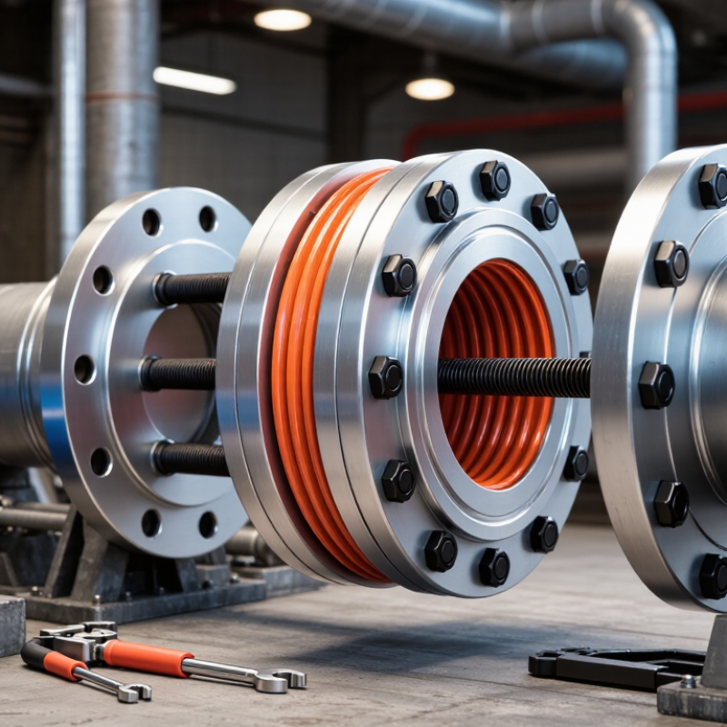
A dismantling joint connects flanged pipes, valves, and other equipment while allowing controlled removal. Its main parts are flanges, a telescopic sleeve, gaskets, and tie rods. The sleeve provides axial adjustment, often a few centimetres, so installers can correct small length differences. Tie rods hold the assembly together and resist separation forces during operation. Without them, internal pressure can push the flanges apart.
PN10 and PN16 are nominal pressure classes, commonly associated with 10 and 16 bar reference ratings. EN 1092-1 flange requirements show why matching flange drilling, dimensions, and pressure class matters. However, PN16 does not guarantee 16 bar in every condition. Temperature, gasket selection, bolt load, pipe material, and surge pressure can reduce the safe working limit. The U.S. EPA’s 2023 Drinking Water Infrastructure Needs Survey estimates $625 billion in investment needs over 20 years, making maintainable joints increasingly important. The WHO/UNICEF Joint Monitoring Programme reported that 2.2 billion people lacked safely managed drinking water in 2022. Small maintenance details carry large consequences.
During installation, technicians should align the pipe first, fit the gasket evenly, and tighten bolts in a cross pattern. Tie rods need balanced tension, not brute force. Field practice is rarely perfect. Misalignment, overlooked thrust blocks, or incorrect bolt tightening can cause leakage. A pressure test should follow the applicable project standard, with results recorded for future inspection.
Dismantling Joint Basics: Flanges, Sleeves, Tie Rods, and PN10–PN16 Ratings
A dismantling joint connects flanged pipe sections and allows controlled axial adjustment during installation and removal. Its flanges transfer the connection load, the sleeve accommodates adjustment, and tie rods help maintain assembly alignment. PN10 and PN16 are nominal pressure classes corresponding to 10 bar and 16 bar respectively; actual allowable pressure depends on temperature, materials, standards, and installation conditions.
How Axial Adjustment Works: Typical 50–100 mm Travel for Pipeline Assembly
A dismantling joint connects flanged pipeline components while allowing controlled axial adjustment. Its central sleeve or telescopic section can move along the pipe axis, usually providing 50–100 mm of travel. This space helps installers align valve faces, pumps, meters, and pipe flanges without forcing the system into position. Tie rods transfer pressure loads and limit unwanted separation. Bolts then lock the joint at the selected length.
During installation, technicians measure the required gap, loosen the joint, and adjust the flange position gradually. A 75 mm movement may correct a difficult connection without cutting or re-fabricating pipe. The gasket must remain centered and evenly compressed. Uneven tightening can create leakage, even when the alignment looks acceptable. The stated travel is typical, not universal. Actual movement depends on diameter, pressure class, temperature, and joint design. It should not automatically be treated as a thermal expansion device.
Tips: Confirm the available travel before ordering. Leave enough clearance for bolt removal and inspection. Tighten opposite bolts in a cross pattern, using verified torque values. Mark the final position for maintenance records. A small correction matters. In practice, installers sometimes assume the full 100 mm is usable under every condition, which is a mistake worth reviewing. Axial movement should be controlled, measured, and checked against the manufacturer’s technical data and the pipeline engineer’s calculations.
Load Transfer and Sealing: Bolts, Gaskets, and DN50–DN2000 Applications
A dismantling joint connects flanged pipework while allowing controlled adjustment during installation. Its telescopic body can absorb small length differences, which helps when valves or pumps need removal. The joint does not simply “hold everything together.” Load transfer depends on its flange design, bolts, and restraint system.
Bolts clamp the mating flanges and create the compression needed for the gasket. In a properly selected assembly, tie rods or restrained bolts can transfer axial forces caused by internal pressure, thermal movement, and pipe weight. The gasket fills tiny surface irregularities around the bore. Its material must suit the fluid, pressure, temperature, and flange finish. A damaged gasket can leak even when every bolt feels tight.
Field practice shows that installation quality matters as much as the joint rating. Pipe ends should be aligned before tightening. Uneven gaps can overload one side of the gasket. Bolts need a controlled, cross-pattern sequence and verified torque. Hand-tightening is not enough. For DN50 systems, compact dimensions may simplify access, but small misalignment remains significant. DN2000 assemblies require lifting plans, staged tightening, and careful inspection of flange faces. One point deserves reflection: a dismantling joint is not a substitute for proper pipe supports or thrust restraint. Its performance changes with the surrounding system, and assumptions about “standard” conditions can become expensive mistakes.
Installation Sequence: Align, Set Clearance, Torque, Pressure-Test, and Remove
What Is a Dismantling Joint and How Does It Work?
Installation Sequence: Align, Set Clearance, Torque, Pressure-Test, and Remove
A dismantling joint connects flanged pipe sections while allowing controlled length adjustment. It also creates space for future valve or pipe removal. Correct installation begins with alignment. Bring both flanges together without forcing the pipe into position. Uneven gaps can transfer stress into the joint and nearby equipment.
Set the specified clearance before tightening the tie rods. Use a steel rule at several points around the joint. The measurement should remain consistent. Tighten bolts in a cross pattern, using a calibrated torque wrench. Apply the required torque in gradual steps. Do not guess by feel. Torque records can help during later inspections. Small details matter.
Pressure-test the assembly according to the approved project procedure. Raise pressure slowly and inspect flanges, seals, and bolt areas. Never stand directly beside a pressurized connection. If leakage appears, depressurize fully before making adjustments. Retorqueing under pressure is unsafe and often ineffective. A pressure test is not complete without written readings and observations.
For removal, support the pipe and connected equipment before loosening the joint. Release pressure and drain trapped liquid first. Mark the original clearance when practical. It helps identify movement during service. In real installations, alignment is not always perfect, and access may be poor. That is why a second measurement is worth the extra minute. Experienced technicians still make errors when they rush. Proper supervision and site procedures remain essential.
Design Standards and Service Limits: EN 545, EN 1092-2, and Water Systems
A dismantling joint connects flanged water-system components while allowing controlled axial adjustment. Its central sleeve, flange rings, gaskets, and tie rods help installers remove valves without cutting pipe. It is not automatically a restraint joint. Tie rods must be designed for pressure thrust, or the pipeline needs separate anchoring. This distinction is often missed in field installations.
EN 545 covers ductile iron pipes, fittings, accessories, and joint performance. EN 1092-2 establishes cast-iron flange dimensions and pressure designations, such as PN10 and PN16. Neither standard gives one universal service limit for every assembly. Engineers must check pipe class, flange rating, gasket material, bolt load, temperature, corrosion allowance, and surge pressure. The U.S. EPA’s 2023 Drinking Water Infrastructure Needs Assessment estimated $625 billion in investment needs over 20 years. WHO and UNICEF reported that 2.2 billion people lacked safely managed drinking water in 2022. Reliable maintenance access matters. A joint that looks oversized may still fail if its gasket is misaligned.
Tips: Confirm the weakest component first. Check the joint’s certified pressure rating, not only the flange marking. During installation, keep flange faces parallel and tighten bolts in a cross pattern. Pressure-test the completed section gradually. Record bolt torque, gasket type, and test results. A practical warning: standards compliance alone does not replace site-specific hydraulic calculations. I would also recheck assumptions about temperature and water chemistry; they are easy to underestimate.