

Choosing a Laser Quenching Machine is not just a matter of comparing power ratings. The right system must deliver repeatable surface hardening, fit the component geometry, and integrate with the factory’s production line. A shaft rotating beneath a focused beam presents different demands from a broad gear tooth or a complex automotive part. Small differences in beam control, scanning speed, and cooling can affect hardness and distortion. Details matter.
Laser-processing expert William M. Steen’s published work provides a useful foundation, but I cannot verify a verbatim quotation from him for this article. A practical paraphrase of the engineering principle is: “Match the laser process to the material, geometry, and required surface properties.” Treat that as a paraphrase, not a direct quote. It is a reminder to ask manufacturers for process data, sample trials, and clear specifications—not simply a catalogue promise.
This guide reviews China’s top 10 laser quenching machine manufacturers through practical buying criteria, including equipment capability, customization, quality controls, technical support, and export experience. Look for evidence: a test report, a documented hardness profile, and a realistic service plan. A polished brochure helps, but it cannot replace a production trial. Some comparisons may remain imperfect because suppliers publish different levels of technical detail. Readers should verify claims directly and assess each machine against their own parts, materials, and production targets.
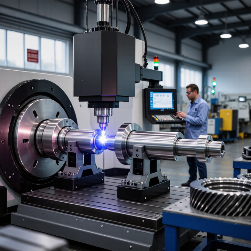
Laser quenching concentrates energy into a narrow surface zone, often at power densities around 10³–10⁵ W/cm². The exact setting depends on the alloy, beam size, surface condition, and travel speed. The range is broad. A small change in focus can shift the heated track from shallow to uneven.
As the beam moves, the surface heats rapidly, while the cooler material beneath it acts as a heat sink. Once the laser passes, heat flows inward and cools the surface without a separate quenching bath. This is self-quenching. If the steel’s composition and thermal cycle are suitable, the transformed surface can develop a hard martensitic layer, while the core remains tougher. Timing matters. Too little energy may leave soft patches; too much can cause melting, roughness, or excessive distortion. In practice, operators check power, spot size, and scan speed together, then inspect hardness and case depth on test pieces. A power-density figure alone cannot predict the result. I would treat it as a starting point, not a recipe; that distinction is easy to overlook.
When assessing Chinese laser-quenching machine manufacturers, look beyond the laser’s rated power. Ask for measured output at the workpiece, including stability during sustained operation. A power meter reading should match the production recipe, not just a catalog figure. Request trial results on your own steel grade and part geometry. Check the hardened layer’s depth and hardness across several points. A glossy sample proves little.
Beam control affects whether heat reaches the intended area consistently. Ask for beam-profile data, focal-position tolerance, and scan-path repeatability. During a factory trial, inspect the treated track under magnification and compare its width at the center and edges. Small variations matter on gears or narrow shafts. Numbers drift. Repeat the test after the machine warms up; this detail is easy to miss.
Automation deserves the same practical scrutiny. Review how the system detects part position, records process settings, and flags an interrupted cycle. The International Federation of Robotics reported 541,302 industrial robots installed worldwide in 2023 in its World Robotics 2024 report. That figure shows broad industrial adoption, not proof that any one machine is reliable. Ask manufacturers to demonstrate a complete unattended cycle, then inspect the alarm log and traceability record. A smooth demo is useful, but it is not a production shift.
The ten profiles compare Chinese manufacturers by engineering capability, not brochure claims. One supplier may focus on compact, cabinet-mounted systems for localized treatment. Another may build larger gantry platforms for shafts, rails, or heavy components. Their differences show up in laser power options, beam delivery, motion accuracy, and cooling design. Fit matters. Ask how each system controls the hardened zone when part geometry changes.
MarketsandMarkets’ 2023 Laser Processing Market report estimated the broader market at USD 6.7 billion in 2023 and forecast USD 11.8 billion by 2028. This covers laser processing overall, not laser quenching alone. Treat it as market context, not a quenching-sales forecast. For each profile, check whether temperature monitoring is closed-loop, whether process recipes can be documented, and what service response is available. A demonstration on a representative workpiece is more useful than a polished video. Small details count. Published specifications may still leave uncertainty about distortion, repeatability, or the actual hardened depth.
China Top 10 Laser Quenching Machine Manufacturers
When comparing ten manufacturers, treat 0.1–2 mm as a practical hardened-depth range, not a guaranteed result from the machine alone. ASM Handbook, Volume 4A, describes laser transformation hardening as a localized process whose outcome depends on the steel and thermal cycle. Power density, scanning speed, beam shape, and surface condition all matter. Small is not simple. A fast scan may produce a shallow layer; slower movement can deepen treatment, but may also increase distortion or soften edges.
Ask suppliers for measured cross-sections, not just brochure figures. A 0.1 mm case may suit a lightly loaded contact surface, while a 2 mm case can better support repeated wear—if the component’s geometry and material allow it. ISO 18203:2016 provides methods for measuring hardened-layer depth in steel, making test results easier to compare. Request the steel grade, hardness profile, scan speed, and measurement method behind each quoted value. These details are sometimes missing. That omission makes a machine-to-machine comparison less reliable, even when the headline depth looks impressive.
Laser quenching suits gears, shafts, guide rails, and other components needing wear-resistant surfaces with tough cores. A controlled beam heats a narrow track, while rapid self-cooling transforms the surface layer. The result depends on alloy composition, initial condition, beam power, and travel speed. Small details matter.
Hardness checks should use a documented test method and calibrated equipment. Measure several locations across the treated zone, not just its brightest-looking section. For thin cases, choose an appropriate microhardness load and prepare the cross-section carefully. A single reading can mislead. Record the base-metal hardness too, since it helps reveal whether the process changed only the intended layer.
Case depth is typically assessed from a polished cross-section, using a defined hardness threshold. Compare measurements at the center and edges of the scan path. Then review process consistency across repeated parts: track overlap, surface scale, fixture position, and temperature monitoring can all affect results. When comparing manufacturers, ask for sample inspection records and the actual acceptance criteria, not only a machine specification sheet. I would still question any claim of perfect uniformity; complex corners and changing section thickness can produce uneven heating. Test representative parts before setting production limits.
Comparison basis: The ten entries below are common laser-quenching application and capability categories, not a ranked list of named manufacturers. Results depend on the workpiece material, geometry, prior heat treatment, and qualified process parameters. Confirm acceptance limits against the component drawing and process specification.
| No. | Application category | Typical workpieces and materials | Hardness check | Case-depth check | Process-consistency checks |
|---|---|---|---|---|---|
| 1 | Automotive transmission and drivetrain parts | Gear teeth, shafts, and splines made from suitable hardenable steels; material grade and initial condition must be verified. | Measure at specified tooth or shaft locations using an approved Rockwell or Vickers method; compare with the part specification. | Use a polished, etched cross-section and a microhardness traverse to determine effective hardened depth against the specified hardness criterion. | Record laser power, scan speed, focal position, track overlap, and part temperature; check representative teeth or features across the batch. |
| 2 | Construction and earthmoving equipment components | Wear surfaces on pins, rollers, sprockets, and selected steel or cast-iron parts, subject to material qualification. | Take readings on defined wear zones and compare them with the drawing or approved control plan. | Section a qualified sample at the specified location; inspect the hardened layer and measure its depth by microhardness. | Verify scan-path coverage, fixture position, surface condition, and temperature feedback; inspect for untreated gaps and overheating. |
| 3 | Machine-tool guideways and slideways | Localized wear tracks on compatible steel or cast-iron machine beds and guide components. | Check hardness at multiple positions along the treated path, including start, middle, and end regions. | Use a cross-section from a representative location to confirm the hardened layer meets the specified depth profile. | Monitor beam alignment, focus distance, travel speed, and overlap; check straightness and distortion after processing. |
| 4 | Hydraulic cylinder rods and piston components | Specified hardenable steel rods, piston surfaces, and related wear-prone regions; coating or plating sequences require process review. | Measure hardness on the treated surface using a method suitable for the part geometry and surface finish. | Check a metallographic cross-section or qualified test coupon using a microhardness profile. | Control rotation or linear feed, beam-to-surface distance, and circumferential overlap; check for uniform coverage around the part. |
| 5 | Railway and transport equipment parts | Selected wheels, axles, and other wear-loaded steel components where localized hardening is permitted by the design. | Measure the specified surface zones and confirm readings meet the approved engineering requirements. | Determine depth on a section taken from a defined sampling location; evaluate the transition from hardened layer to core. | Maintain traceable process records and verify repeatability on qualified samples; inspect treated-area boundaries and part distortion. |
| 6 | Mining and mineral-processing equipment | Wear edges, teeth, shafts, and other compatible steel or cast-iron components exposed to abrasive service. | Check hardness at multiple points across the specified wear surface rather than relying on a single reading. | Use a sectioned sample and microhardness traverse to verify the hardened zone and its transition into the substrate. | Check surface preparation, scan overlap, thermal monitoring, and repeatability between parts; inspect for cracks and localized melting. |
| 7 | Agricultural machinery components | Wear areas on shafts, gears, rollers, and tillage components made from laser-hardenable grades. | Measure at the designated contact or wear locations using the specified hardness scale and test method. | Confirm effective depth on a representative cut section or qualified coupon using the agreed hardness threshold. | Control part positioning and scan trajectory; verify consistent coverage on repeated features and inspect for edge overheating. |
| 8 | Oil, gas, and fluid-handling equipment | Selected valve stems, pump shafts, sleeves, and other compatible components requiring localized wear resistance. | Test the treated region at defined locations and document the method, load, and measurement position. | Measure the hardened layer on a metallographic section; confirm the sampling location represents the critical service surface. | Monitor laser and motion-system records, surface temperature where applicable, and scan overlap; verify batch traceability. |
| 9 | Power-generation and heavy-industry parts | Selected shafts, bearing seats, and large steel or cast-iron components with localized hardening requirements. | Use a test method appropriate to the component size and geometry; map readings across the specified treated zone. | Assess case depth on a representative section or qualified witness sample; relate the result to the specified criterion. | Check long-path scan stability, focus distance, thermal history, and fixture movement; inspect for distortion and untreated areas. |
| 10 | Custom tooling and repair applications | Localized regions on compatible dies, molds, tooling, and repairable steel or cast-iron parts after material and repairability review. | Take hardness readings within and around the treated area to assess the hardened zone and adjacent material. | Qualify depth on a representative sample or repair procedure; use cross-sectional microhardness where required. | Document the approved repair path, parameter window, number of passes, and inspection results; check for cracking and excessive heat-affected areas. |
TERMS OF USE - LEDOLUX
This site uses cookies in order to deliver services in accordance with Privacy Policy. You can use settings within your browser to control the cookies that are set on your computer – conditions of access or storage of cookies.
Your data controller will be LEDOLUX POLAND SP. ul. Innowacyjna 1; 36-060 Głogów Małopolski, which adapts the content of its website to your needs and analyses and examines them to improve it. More information.