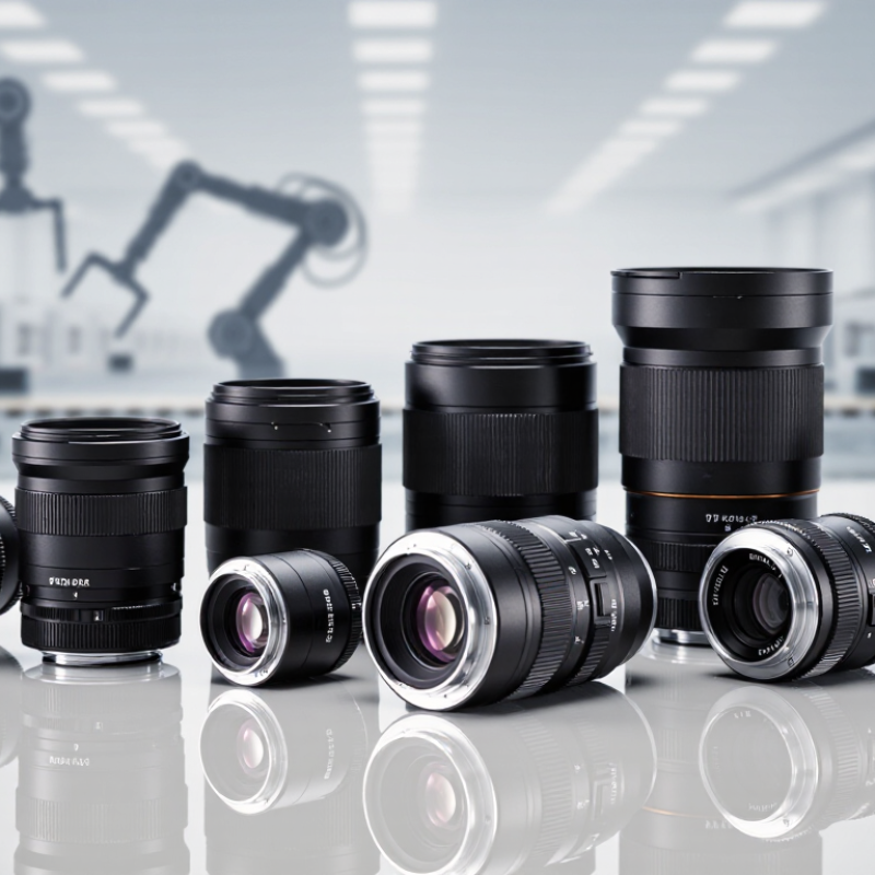
Choosing a telecentric lens in 2026 requires more than comparing magnification and price. Global buyers must examine optical design, sensor size, working distance, illumination, and measurement tolerance. A bi telecentric lens can keep object and image-side rays nearly parallel. This helps reduce perspective errors when inspecting edges, holes, connectors, and molded parts.
This introduction explores the leading types available to international machine-vision users. It considers object-space, image-space, and dual telecentric designs. It also discusses fixed-magnification models, variable-magnification systems, coaxial-light versions, and lenses built for large field measurements. Each type serves a different inspection condition. A compact lens may fit a crowded production cell. A long-working-distance model may protect the optics from heat, dust, or moving components.
Practical selection should begin with verified measurements, not attractive catalog language. Buyers should request distortion data, telecentricity limits, depth of field, coating details, and tested image samples. Independent calibration can reveal errors that a specification sheet hides. Small alignment changes matter.
There is no universal best lens.
Manufacturers may define telecentric performance differently. Regional distributors may also describe similar designs inconsistently. That issue deserves attention. This guide therefore compares published specifications with real application needs, including lighting geometry, camera compatibility, installation space, and service support. It aims to help engineers, integrators, and purchasing teams make defensible decisions. Some recommendations may still require testing. Optical performance depends on the complete imaging system, not the lens alone.
A bi-telecentric lens is designed to keep light rays nearly parallel on both sides of its optical system. This dual telecentric structure controls perspective distortion during image capture. An object can move slightly toward or away from the lens without changing its measured size significantly. That matters when a production line checks metal parts, molded components, glass edges, or electronic connectors.
Global buyers often need reliable dimensional data across different factories and operating conditions. A bi-telecentric lens helps reduce measurement variation caused by object height changes. Its stable magnification also supports repeatable inspection with cameras and calibrated software. For example, a 20-millimeter feature can remain visually consistent across a defined depth range. This makes edge detection more dependable. It also reduces errors when operators cannot position every part perfectly.
Selection still requires careful engineering. A lens is not a magic fix. Buyers should compare sensor size, pixel pitch, working distance, field of view, and required accuracy. Lighting must match the lens, especially for reflective surfaces or transparent materials. In practice, teams sometimes choose a wide field of view and lose useful resolution. That mistake is easy to overlook. Environmental vibration, temperature changes, and mounting alignment can also affect results. Testing sample parts before purchase is wiser than trusting specifications alone. A practical evaluation should record repeatability, edge sharpness, and measurement drift over several hours.
Object-space and image-space telecentric designs solve different imaging problems. Object-space telecentricity keeps chief rays parallel before they reach the lens. This stabilizes magnification when an inspected part moves slightly along the optical axis. It is valuable for measuring holes, edges, and molded components.
A practical example is a metal washer that sits two millimeters above its expected position. Its diameter can remain visually consistent.
Image-space telecentricity keeps rays parallel between the lens and the camera sensor. This design helps deliver uniform illumination across sensor pixels. It can also reduce shading and improve measurement consistency near the image edges.
However, it does not automatically control object-side magnification. Buyers should check which side requires geometric stability. The answer depends on the machine structure, not only the camera resolution.
A bi-telecentric lens combines both conditions. It can provide strong dimensional accuracy, low perspective error, and stable imaging through small position changes.
In production, this matters when fixtures wear or parts arrive imperfectly. I have seen teams overestimate its benefits, though. Working distance, field of view, lighting, and depth of field still limit performance.
Some designs also transmit less light than conventional lenses. That trade-off is easy to miss during procurement. Request measured data, not only catalog claims. A careful trial with real parts often reveals small edge errors that laboratory targets hide.
2026 Top Types of Bi-Telecentric Lenses for Global Buyers
Bi-telecentric lenses keep chief rays nearly parallel on both object and image sides. This design reduces perspective errors during dimensional inspection. Fixed-magnification bi-telecentric lenses suit precision gauging, where a 10 mm feature must remain 10 mm across the field. They are common in checking machined parts, connectors, and molded components.
Coaxial-illumination bi-telecentric lenses provide even light along the optical axis. They help inspect flat surfaces, etched markings, and printed circuit patterns with fewer shadows. Large-format versions support wider fields for trays, panels, and multiple parts in one image. High-resolution types reveal small edges, but they may require stronger lighting and careful vibration control. No lens solves every setup.
For transparent or semi-transparent components, specialized bi-telecentric systems can improve edge visibility when paired with backlighting. This is useful for measuring glass tubes, films, syringes, and small molded parts. Buyers should compare magnification tolerance, working distance, sensor size, depth of field, and distortion data. Experience shows that a longer working distance often improves access, yet it can increase system size and cost.
Tips: Use a calibrated target before production testing. Check edge contrast at the real working distance. Test the smallest feature, not only the clearest sample. A lens that looks excellent in a catalog may perform poorly under uneven lighting. Recheck alignment after installation.
Key telecentric lens architectures and their typical imaging applications. A value of 1 indicates that telecentricity is provided on the corresponding optical side; 0 indicates that it is not.
Application guide: Object-space telecentric lenses are commonly used for dimensional inspection, image-space telecentric lenses help reduce sensor-side perspective and chief-ray effects, and bi-telecentric lenses provide telecentricity on both sides for high-accuracy gauging, metrology, and precision machine vision.
2026 Top Types of Bi Telecentric Lenses for Global Buyers
Comparing bi-telecentric lenses starts with the optical path, not the product label. A true bi-telecentric design keeps magnification stable when object distance changes. Check telecentricity error, distortion, numerical aperture, and usable image-circle size. A large sensor needs full coverage. Otherwise, edge measurements may look accurate but remain incomplete. Magnification and working distance must also suit the part, lighting, and camera resolution. For fine scratches, higher resolution helps, but it can reduce depth of field.
Mechanical specifications decide whether that optical performance survives installation. Review lens length, mass, mounting thread, aperture control, and flange distance. Confirm that the camera mount can support the assembly without flexing. Coaxial illumination may require extra clearance around the lens. In a vibrating production cell, a lightweight lens can be easier to install, yet its mount may need stronger support. This trade-off is often missed.
Compatibility checks should include sensor format, pixel size, spectral range, connector clearance, and software calibration needs. Visible-light models may not perform equally under near-infrared illumination. Ask for measured data, not only nominal values. Factory acceptance tests should use calibrated targets, real part heights, and the intended exposure settings. A spreadsheet helps. It is not enough. Engineers sometimes compare distortion figures from different test methods, creating a false advantage. Recheck definitions, tolerances, and environmental limits before purchasing across regions.
| Bi-Telecentric Lens Type | Typical Magnification Range | Working Distance | Object-Space Telecentricity | Image-Space Telecentricity | Typical Resolution Capability | Recommended Sensor Format | Mechanical Configuration | Illumination Compatibility | Typical Applications | Key Buying Considerations |
|---|---|---|---|---|---|---|---|---|---|---|
| Low-Magnification Inspection Bi-Telecentric Lens | Approximately 0.1×–0.5× | Typically 100–250 mm | Very low chief-ray angle; minimizes apparent size changes caused by object-height variation | Very low chief-ray angle at the sensor; supports stable scale across the image field | Commonly suitable for precision measurement when matched with an appropriate camera and lighting system | 1/2 in, 2/3 in, 1 in, and larger sensors, depending on image circle | Usually C-mount or larger industrial camera interfaces; fixed-focus barrel; front and rear mounting threads may be provided | BacklightCollimated lightRing light | Large mechanical parts, stamped components, dimensional inspection, edge measurement, and presence checks | Check field of view, object clearance, image-circle diameter, and whether the camera sensor is fully covered |
| Medium-Magnification Metrology Bi-Telecentric Lens | Approximately 0.5×–1.5× | Typically 65–150 mm | Designed for low measurement error from moderate object-position changes | Maintains nearly constant magnification over the usable sensor area | Often selected for sub-pixel edge measurement; practical accuracy depends on optics, calibration, lighting, and camera sampling | 2/3 in, 1 in, 1.1 in, and compact area-scan sensors | Rigid metal housing with fine focus or adjustable mounting; commonly used with machine-vision camera adapters | Telecentric backlightCoaxial lightDark-field light | Connectors, molded parts, seals, precision holes, flatness checks, and dimensional gauging | Compare distortion, telecentricity error, depth of field, numerical aperture, and calibration repeatability |
| High-Magnification Bi-Telecentric Lens | Approximately 1.5×–5× | Typically 35–100 mm | Strong control of perspective error for small, precision-critical features | Supports consistent feature scale at the image plane, subject to the specified sensor coverage | Suitable for fine-feature inspection when paired with a high-resolution camera and stable mechanics | 1/2 in, 2/3 in, 1 in, and selected high-resolution sensors | Usually larger and heavier than low-magnification optics; may require a rigid lens mount and vibration control | Coaxial lightBright-fieldMicroscopic illumination | Micro-connectors, semiconductor packages, precision apertures, small molded features, and fine surface inspection | Verify pixel size, required field of view, working distance, depth of field, and mechanical load capacity |
| Large-Format Bi-Telecentric Lens | Approximately 0.05×–1.0× | Typically 100–400 mm | Low perspective sensitivity over a wide object area | Designed to cover large image sensors with low angular variation | Resolution varies substantially with field size; edge performance must be evaluated across the complete image circle | 1.1 in, 4/3 in, APS-C, and other large-format sensors when the specified image circle is sufficient | Large outer diameter and high mass are common; requires reinforced camera and lens support | Large-area backlightCollimated illuminationArea lighting | Automotive components, large machined parts, battery components, sheet materials, and wide-field dimensional inspection | Confirm image-circle diameter, flange distance, mount strength, illumination uniformity, and total system envelope |
| Coaxial-Illumination Bi-Telecentric Lens | Approximately 0.1×–2× | Typically 65–200 mm | Preserves dimensional stability for front-facing inspection | Reduces image-scale variation caused by sensor-side ray angles | Optical performance depends on beam-splitter design, aperture, coating quality, and sensor matching | Commonly 2/3 in, 1 in, and larger area-scan sensors | Integrated beam splitter or coaxial port; housing must allow access for lighting and camera alignment | Coaxial LEDOn-axis lightPolarized light | Flat reflective surfaces, wafers, glass, labels, printed patterns, and precision surface features | Check light-port geometry, beam-splitter transmission, polarization requirements, working distance, and glare control |
| Variable-Magnification Bi-Telecentric Lens | Typically adjustable across a limited range, such as 0.3×–0.6× or 0.5×–1.0× | Usually fixed or nearly fixed within the adjustment range | Maintained across the specified magnification settings when correctly adjusted | Maintained within the manufacturer’s stated operating range | Performance can change with magnification; recalibration is required after changing the optical setting | Sensor compatibility depends on the image circle at every adjustment position | Adjustable optical groups, locking rings, and a more complex housing; requires repeatable positioning | Backlight, coaxial, ring, and diffuse dome illumination, depending on the front optical design | Multi-part inspection stations, prototype lines, flexible automation, and applications with changing field-of-view requirements | Evaluate repeatability of the adjustment mechanism, locking method, recalibration needs, and edge performance at each setting |
| Compact Bi-Telecentric Lens for Space-Limited Machines | Approximately 0.1×–1× | Typically 40–100 mm | Provides perspective control within a compact optical envelope | Designed to maintain stable magnification within the supported sensor area | Often optimized for moderate-resolution industrial inspection rather than the largest image formats | Commonly 1/2 in, 2/3 in, and 1 in sensors | Short optical length and reduced outer diameter; commonly paired with compact cameras and enclosed fixtures | Compact backlight, coaxial light, ring light, or integrated illumination modules | Robotic cells, compact gauging equipment, electronics inspection, and confined production fixtures | Compare total length, outer diameter, mounting-hole pattern, cable clearance, thermal stability, and service access |
| Long-Working-Distance Bi-Telecentric Lens | Approximately 0.05×–0.8× | Typically 200–500 mm or more | Maintains low perspective error while leaving clearance for tooling, robotics, or protective windows | Provides stable image scale when the camera and lens are correctly aligned | Resolution is influenced by the long optical path, aperture design, vibration, and atmospheric conditions | 2/3 in, 1 in, 1.1 in, and larger sensors according to the specified image circle | Longer barrel and larger support requirements; rigid mounting and vibration isolation are especially important | Remote backlightStructured lightLarge-area LED | Hot or moving parts, deep assemblies, robotic inspection, large fixtures, and applications requiring tool clearance | Check vibration sensitivity, environmental sealing, protective-window effects, lighting distance, and mounting rigidity |
| High-Resolution Line-Scan Bi-Telecentric Lens | Application-dependent; commonly about 0.1×–1× | Typically 100–300 mm | Reduces perspective distortion across the measured line | Helps maintain consistent magnification along the sensor line when alignment and focus are controlled | Selected according to line-pair performance, sensor pixel pitch, scan speed, and required measurement accuracy | Line-scan sensors with the required active length and pixel pitch; image-circle coverage is critical | Requires precise alignment with the scan line, encoder system, and machine-motion direction | Continuous line light, telecentric backlight, and synchronized strobed illumination | Web inspection, film and foil measurement, flat-part inspection, battery electrode inspection, and continuous production lines | Verify sensor line length, scan direction, depth of field, distortion, working distance, and illumination synchronization |

In 2026, global buyers are comparing bi telecentric lenses by more than magnification and price. The right choice depends on inspection accuracy, application distance, sensor size, and production speed. A lens may fit a catalog specification yet fail beside a vibrating machine. Measure twice. Check the working distance under real lighting, not only in a spreadsheet.
Quality should be verified through repeatability tests, edge clarity, distortion data, and stable mechanical construction. Buyers should request inspection reports, dimensional drawings, and optical performance records before approval. Relevant safety, electrical, and quality standards also deserve careful review. Requirements differ between markets and industries. Do not assume one certificate covers every installation. In my experience, sample testing reveals weaknesses that polished documents can hide.
Reliable support affects the total cost of ownership. Ask about calibration guidance, replacement availability, integration advice, and response times across time zones. A lower purchase price can become expensive after shipping delays, rework, or frequent adjustments. Support matters. Buyers should compare warranty terms, packaging protection, import costs, maintenance needs, and expected service life. Our own evaluations are not always perfect; early estimates sometimes overlook operator training and fixture changes. That is why a small pilot order, with recorded results, is often wiser than a large commitment.
TERMS OF USE - LEDOLUX
This site uses cookies in order to deliver services in accordance with Privacy Policy. You can use settings within your browser to control the cookies that are set on your computer – conditions of access or storage of cookies.
Your data controller will be LEDOLUX POLAND SP. ul. Innowacyjna 1; 36-060 Głogów Małopolski, which adapts the content of its website to your needs and analyses and examines them to improve it. More information.